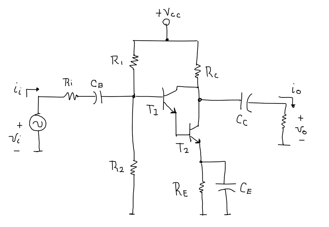
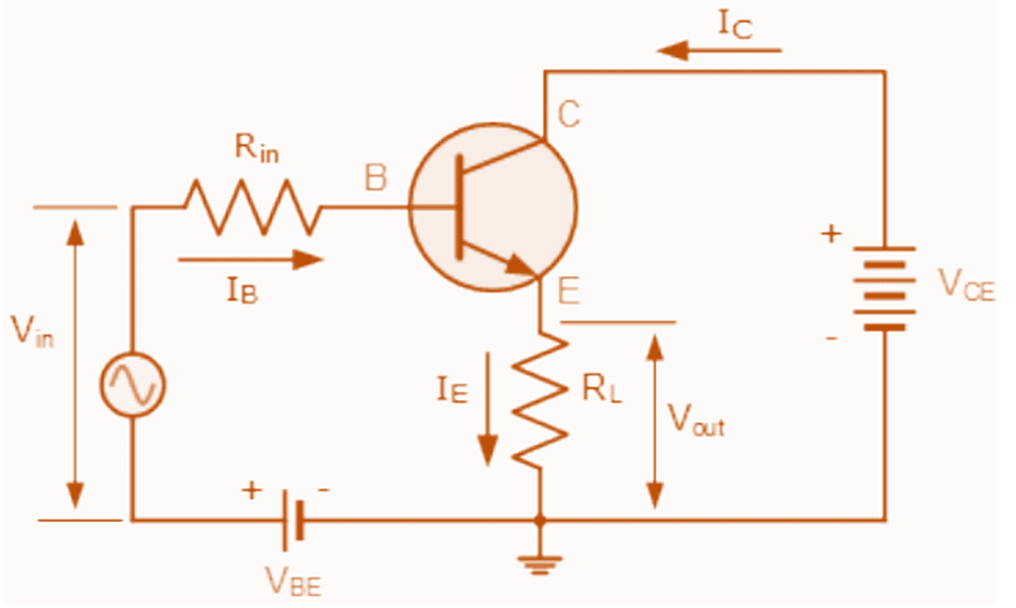
Solved For the circuit with two BJT transistors Circuit Diagram The Bipolar Junction Transistor or BJT, is a solid-state current-controlled device which can be used to electronically switch a circuit, you can think of it as your normal Fan or Light switch, but instead of you turning it on manually it can be controlled electronically. Technically speaking, BJT is a three-terminal device with an Emitter

What is a Bipolar Junction Transistor (BJT) and how does it work? The transistor is classically defined as a three-terminal semiconductor device that operates as a linear amplifier, oscillator, or digital switch. To intuitively understand transistors, you will need to build a circuit. Start by building the beginner transistor circuits

Understanding Bipolar Junction Transistors (BJTs) in EE 221 Circuit Diagram
What is a Bipolar Junction Transistor (BJT)? A bipolar junction transistor( BJT) is a directly junctioned electronic device generally applied in revision and switching circuits. It's composed of alternate layers formed by either P- type or N- type semiconductors and comprises three regions: the emitter, the base, and the collector. EE 221 BJT: Structure A BJT is a sandwich of three regions of semiconductor, each with a different doping. Each region is connected to a terminal of the transistor. Here is the structure of an npn BJT. • Emitter: Heavily doped (here n-type. The emitter injects its majority carriers (electrons) into the base. • Base: A very thin region that controls the flow of the injected charge carriers. Variability in Current Gain: β can vary widely among transistors of the same type. Saturation Mode: In saturation, R CE approaches zero, causing V CE to be almost zero. Frequently Asked Questions 1. What is the purpose of using a BJT in a circuit? A BJT can act as an amplifier to increase signal power or as a switch to control circuit flow. 2.

In the second installment of this series, we will explain Vceo (collector-emitter voltage) and Vces (collector-emitter breakdown voltage).. Collector-emitter voltage Vceo. Vceo is the breakdown voltage when the depletion layer that spreads from the base to the emitter and the depletion layer that spreads from the EB junction to the base collide. (See Figure 5 on the left below) How To Choose a Transistor. The NPN transistor is the most common of the Bipolar Junction Transistors (BJT).But there is another one called a PNP transistor that works the same way, just that all the currents are in the opposite direction.. When choosing a transistor, the most important thing to keep in mind is how much current the transistor can support.

A Getting Started Guide for Beginners Circuit Diagram
device and it comes in two general types: the Bipolar Junction Transistor (BJT) and the Field Effect Transistor (FET). Here we will describe the system characteristics of the BJT configuration and explore its use in fundamental signal shaping and amplifier circuits. The BJT is a three terminal device and it comes in two different types. The npn
