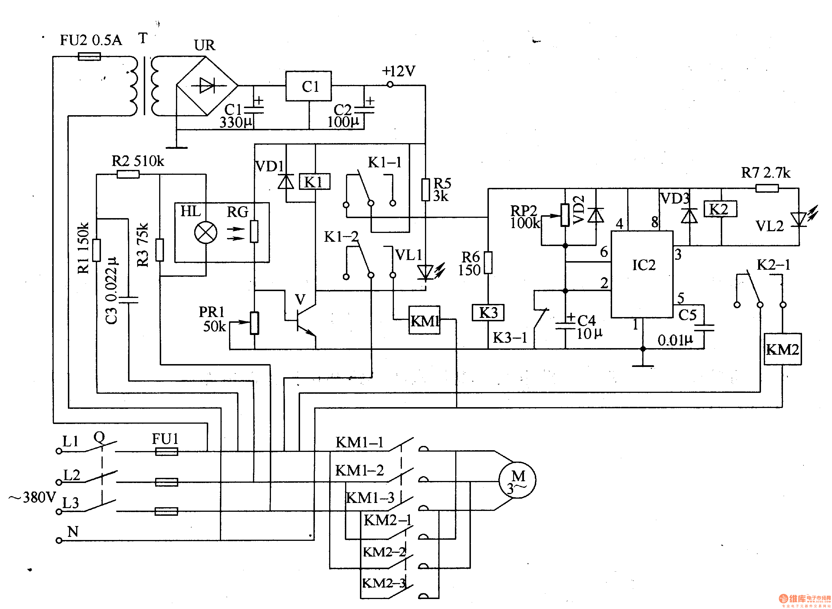
Motor Protection Scheme Circuit Diagram A motor protection circuit breaker, or MPCB, is a specialized electromechanical device that can be used with motor circuits of both 60 Hz and 50 Hz.It has several functions that allow it to provide a safe electrical supply for motors: Protection against electrical faults such as short circuits, line-to-ground faults and line-to-line faults. The MPCB can interrupt any electrical fault that is
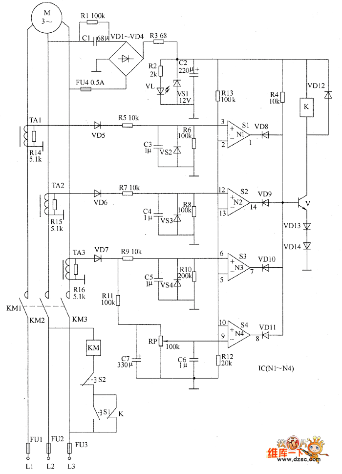
The document discusses the design basics of motor protection circuit breakers. It describes how they combine short-circuit protection and motor overload protection. The key components are a thermal overcurrent release, electromagnetic overcurrent release, and main contact system. The thermal release protects against overloads like a bimetal relay, while the electromagnetic release quickly
PDF Circuit Protection Methods Circuit Diagram
The entire circuit explanation is provided over/under cut-off voltage circuit. 2) DC Motor Over Heat Protection Module Circuit. The third problem involving temperature rise of the motor can be solved by integrating the following simple temperature indicator circuit. This circuit was also covered in one of my earlier posts.
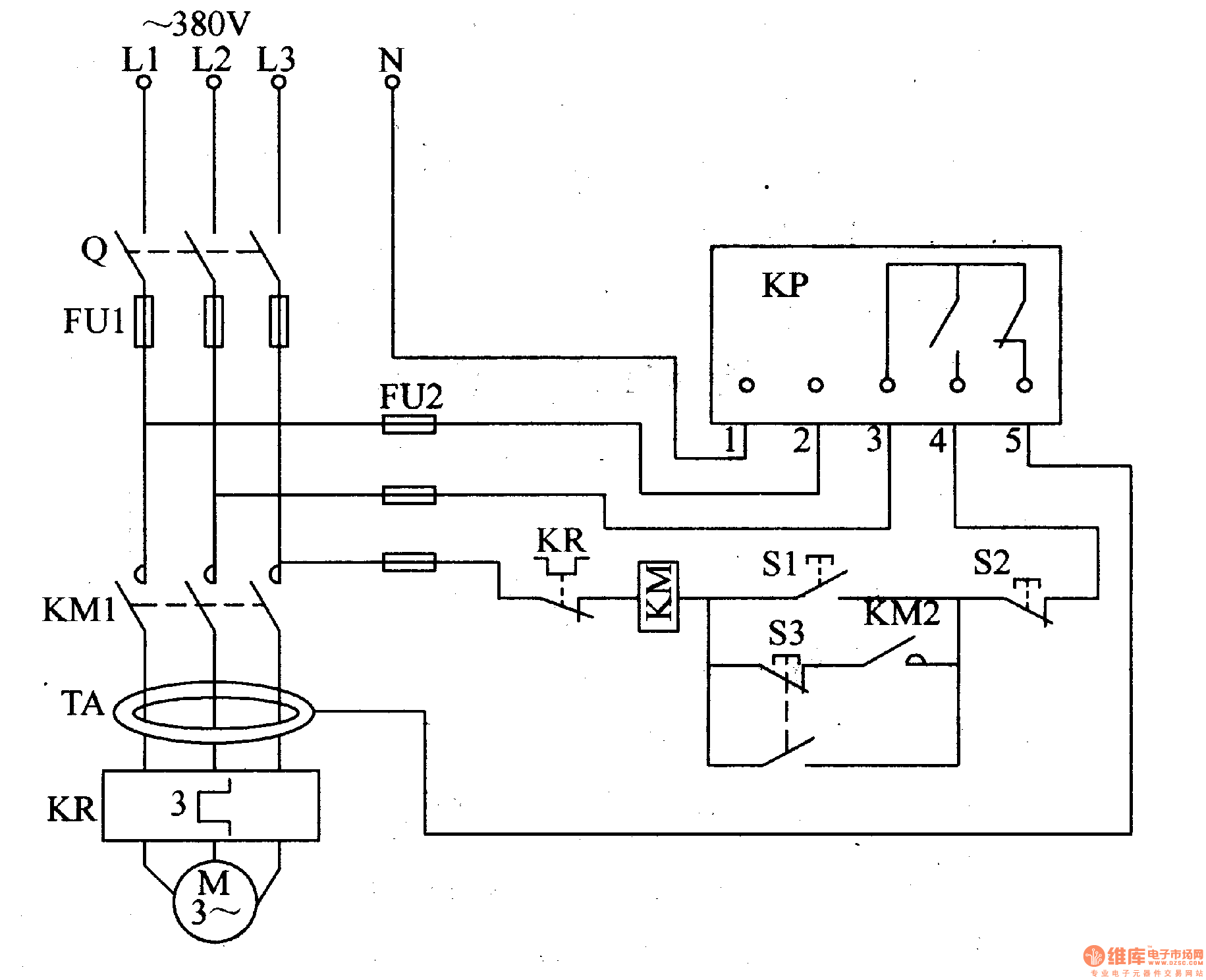
Motor Protection Circuit Breakers Motor Protection Circuit Breakers (MPCBs) combine the short-circuit and isolation functionality of a molded case circuit breaker with the motor overcurrent protection of a traditional overload relay. These devices are traditionally used in two-component starter applications, with a contactor to control a motor MPCB is the electromechanical protection device which is specially designed for motor protection. It is combination of two function like as one is adjustable overload relay and circuit breaker. It is the latest device of motor protection. Generally overload and circuit breaker are used as separately. 2- Circuit diagram of MPCB:

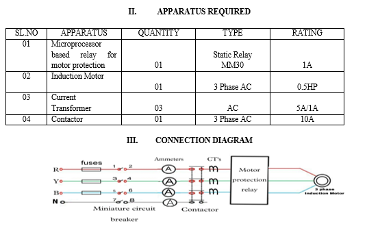
PDF Motor Starting, Protection and Control Circuit Diagram
• Basic and advanced protection functions. • Motor Heating. • Pump Cleaning • Limp Mode • Motor Jogging and Breaking • Torque Control • 18 - 370A • Built in bypass. • User friendly HMI • Torque control. • Current limit (1.5-7*Ie) • Basic motor protection functions. • Analogue output. • Optional communication —