LED Blinker Circuit Simple mini projects in Electronics Inhouse Circuit Diagram Using a relay is the most simple blinking led circuit. How to Make Blinking LED Circuit with Transistor. We can utilize a transistor as a switch when we operate it on its active and cut-off region. This time we will use an NPN transistor to make LED flashing in sequence. How to Make Blinking LED Circuit with Microcontroller.

Blink an LED using PIC16F84A and CCS PIC C compiler. This topic shows a simple example for making an LED blinks using Microchip PIC16F84A 8-bit microcontroller and CCS PIC C compiler. It is easy to make an LED blinking, a few program lines are required and the microcontroller PIC16F84A is a simple chip also. LED: Light Emitting Diode. Hardware This microcontroller has also 10-bit, up to 8-channel Analog-to-Digital Converter (A/D) and many other peripheral features. Blink an LED using PIC16F877A and CCS C compiler: This is a small example shows how to make an LED blinking. Circuit schematic is shown below:
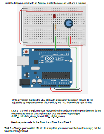
Blinking LED Circuit with Schematics and Explanation Circuit Diagram
In this tutorial we will build a small circuit on a Perf Board for Blinking the LED using PIC. We will dump the program to our PIC microcontroller and verify the LED Blinking. To Program the PIC MCU we will be using MPLAB IPE. ICSP is a simple way which helps us to program an MCU even after it is placed inside our Project board. There is no LED Blinking Code MikroC Pro To simulate the circuit as per our desired function i.e. for the LED to blink, the microcontroller PIC16F877A needs to be programmed with a relevant C-code. Write the following LED Blinking code in the mikroC compiler. If you don't have experience with MikroC pro, you can read this post:

The while(1) defined inside is simple endless loop that keep executing the block inside the braces. For our blinking project we have defined two led's to blink simultaneously together using LATB Register. LATBbits.LATB0 = 1; // RB-0 to High LATBbits.LATB1 = 1; // RB-1 to High delayzz(); // calling the delay function. Welcome to my guide on creating your first microcontroller LED blink project! As an experienced programming educator, I have led thousands of students on their journey into the world of hardware hacking. The basic LED circuit connects to Arduino pins like so: Anode (+)-> 220Ω resistor -> Arduino Pin 13 . Cathode (-)-> GND. Here is a If you haven't already, create a new project in MPLAB, copy the program text into the main. asm file, assemble it and load to the microcontroller. You will see the blinking LED2 with the frequency close to 4Hz.
