How to Make an Led Pulse Circuit 3 Steps Circuit Diagram This circuit may be converted into a negative-edge pulse detector circuit with only a change of the final gate from AND to NOR: Now that we know how a pulse detector can be made, we can show it attached to the enable input of a latch to turn it into a flip-flop. In this case, the circuit is a S-R flip-flop: The frequency and the decay of the oscillation is influenced by metal in proximity of the coil. For further details of the circuit see the page of Teemo or of TechKiwi here on Instructables. As in the Flip Coil Pulse Induction detector I use the internal comparator and the possibility to trigger an interrupt to acquire the signal from the coil. Design Example: Level-to-Pulse • A level-to-pulse converter produces a single-cycle pulse each time its input goes high. • It's a synchronous rising-edge detector. • Sample uses: - Buttons and switches pressed by humans for arbitrary periods of time - Single-cycle enable signals for counters Level to Pulse Converter L P CLK Whenever
The high pass filter created by the 1k resistor and 10uF capacitor (Step 7) is not very well tuned for the pulse frequency. The cut-off frequency for the 1k resistor and 10uF capacitor is about 16Hz which is well above the pulse frequency of 1.2Hz. Unfortunately, I simply overlooked this when first making the circuit. What I found were forums packed with very intelligent people working on homebrew detectors, schematics, circuits, and designs with the electrical engineering knowledge to make very interesting and cost effective metal detectors. I was delighted to find several schematics for Pulse Induction, VLF, and CCO detectors on the Geotech forum.

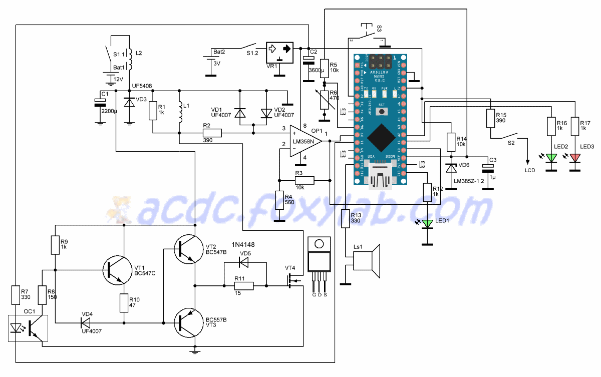
Arduino Based Pulse Induction Detector Circuit Diagram
Using this circuit you will having a working PI detector with only 8-10 external components (depending if the OLED display and/or a speaker is used). Step 4: Setting Up and Using the Detector If the detector is build properly and the program is written to the Arduino, the easiest (if not the only) way of setting the unit up is to use an OLED
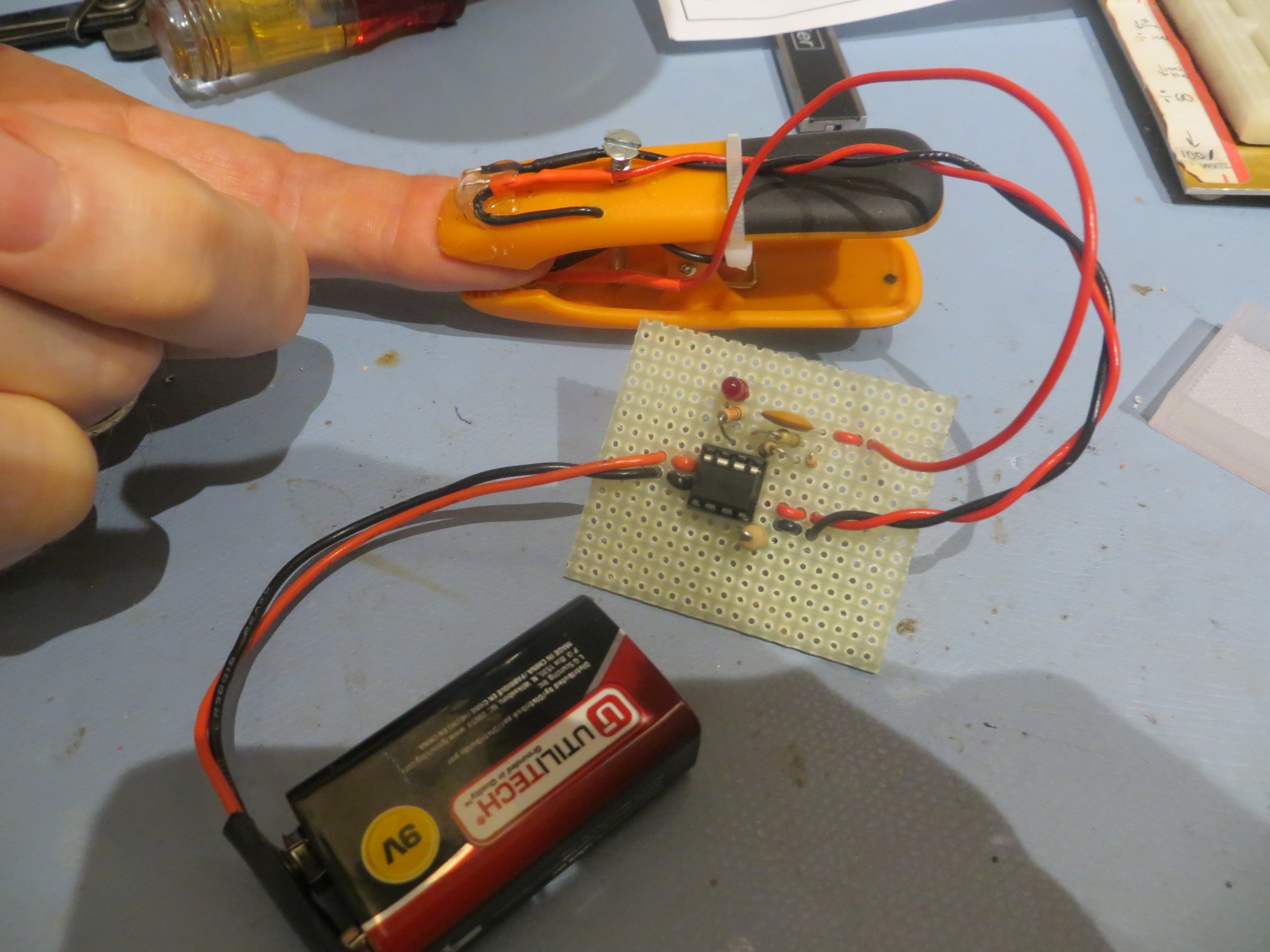
The deep penetration and wide coverage area of pulse induction detectors also make them ideal for searching in large open spaces, such as fields or parks, where targets can be spread out over a wide area. Step 3: Assembling the Circuit. pulse induction metal detector, circuit, assembling, step-by-step guide, building, components, connection
Button, Pulse Detector, and Pulse Generator Solutions Circuit Diagram
Otherwise, the output pulse width will be same as the input pulse width. That is without Q3 transistor, the output pulse follows the input pulse. The R and C values used are 47KOhm and 47uF each which gives a pulse width of 2.2 seconds. You can use the online RC time constant calculator to find out the R and C values for give time period. The
