circuit Protection Circuit crazyelectro electronics Circuit Diagram With 1694 Electronic Circuit Protection the disconnection of the load happens electronically by a transistor. The trip characteristics of a 1694 Electronic Circuit Protector tolerates a momentary inrush current from e.g. switching on a capacitive load and limits the maximum current. In case of a current being too high for too long the 1694 Thermal Cutoffs: As opposed to most other circuit protection devices, thermal cutoffs rely on mostly external (non-circuit) input to trigger circuit protection. Thermal cutoff fuses often rely on a one-time fusible link that, when exposed to ambient temperature over the melting temperature of the link, will fail to protect the circuit.

Figure 3. Protecting against voltage surges with a traditional TVS solution. In-Line Fuse. Overcurrent protection can be implemented using the ubiquitous in-line fuse with a fuse blow rating at some margin above nominal—for example, 20% higher than the max rated current (the percentage will depend on the type of circuit as well as the typical operational loads expected). The protection of the circuit can be done by using different protection devices in an electrical circuit purposely in order to stop extreme amounts of current. To make sure extreme safety, this article gives an overview of circuit protection techniques , namely circuit breakers, ESD protection electronic fuses, gas discharge tubes, thyristors Circuit protection refers to the comprehensive set of mechanisms and devices designed to safeguard electronic circuits from a wide range of potential threats. It acts as an impenetrable shield, shielding your circuits from overcurrent, voltage spikes, and various other electrical anomalies that can wreak havoc on your devices.
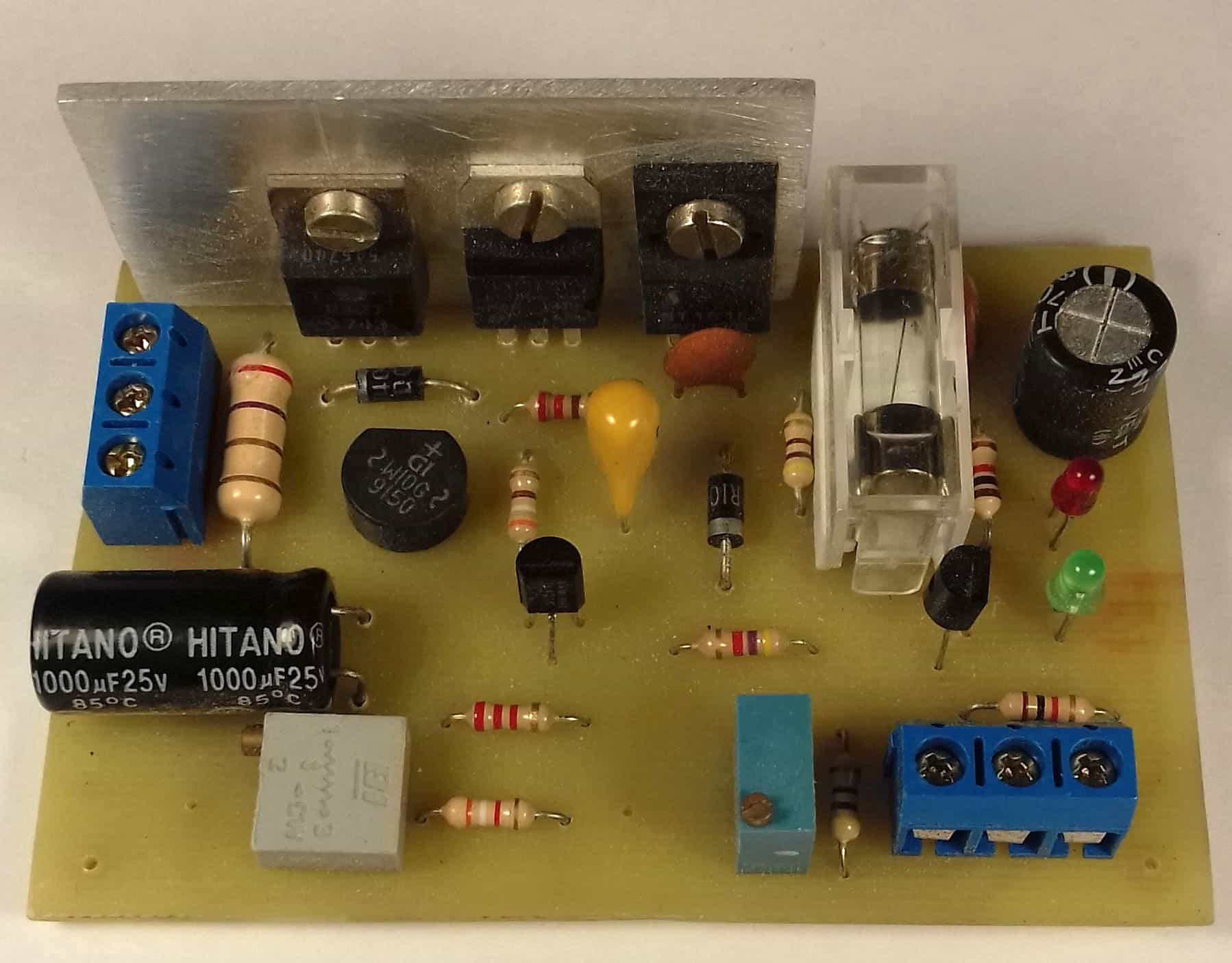
Electronic Circuit Protection Circuit Diagram
Circuit Protection Methods Differentiating between Supplementary Protection, Branch Circuit Protection, and Self-Protected Devices Introduction Modern electrical equipment continues to increase in complexity and importance in industrial, commercial, and residential installations. This equipment is often considered critical for normal system
Many circuit protection techniques are often concerned with outside effects, but sometimes circuits need to be protected from themselves. One classic example of self-protection is short circuit protection with the use of a fuse.While not all circuits suffer from this problem, some designs may incorporate circuitry that has the potential to draw large amounts of current during fault conditions. Learn how to protect your electronic devices from overvoltage, overcurrent, and heat with expert tips on circuit protection methods from Mark Harris. Overvoltage, overcurrent, and heat are the three most likely events that can destroy our expensive silicon-based components or reduce our product's life expectancy.