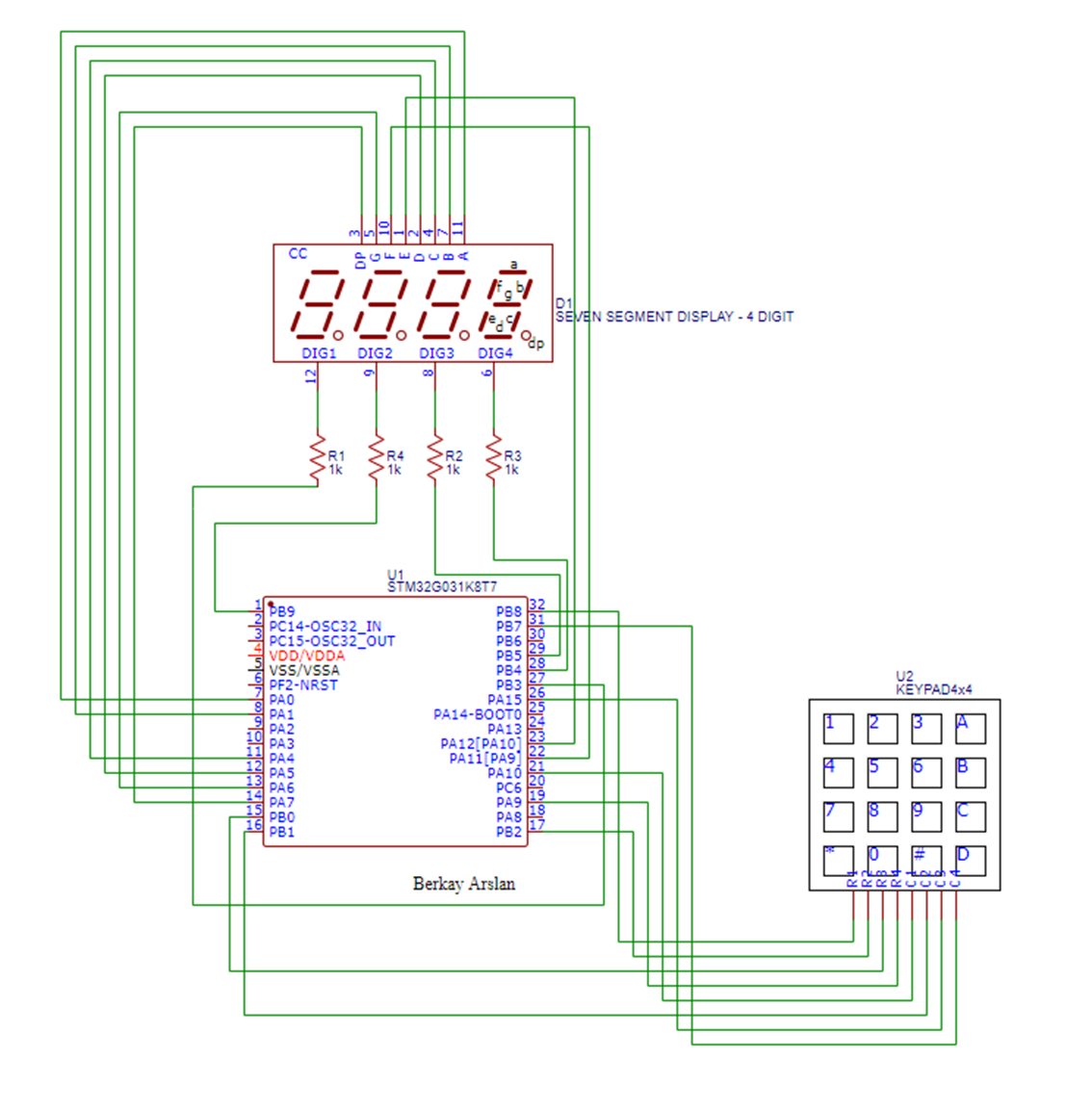
based complex calculator through Arduino IDE and Circuit Diagram Features of this PIC Microcontroller based Calculator: You can give any single digit input from 0 to 9. You can press the 'ON/C' button at any time to reset the calculator. In the PIC calculator project, mathematical operation perform in switch case as per the operators. Moreover, it will always reset when you try to calculate new value. As its a simple calculator, so its only limited to 1 digit, means it will only apply the operation on single digit input like 2+3 but it won't work on more than 1 digit like 12 + 13. I will soon design a more complicated calculator but for this one its only limited to single digit.

Calculator with Pic 16f877 microcontroller is a comprehensive project. Comprehensive in the way that code is lengthy and logical. It will be hard for newbies to understand the code and circuit components interface with pic microcontroller. I will try to explain each and every thing about code and circuit thoroughly. The project covers all the aspects… In this tutorial i am going to build a simple two digit calculator with 8051(89c51,89c52) microcontroller. Calculator takes two single digits and an operator as input and produces output. Input is taken by 4×4 numeric keypad and output is displayed on 16×2 character lcd. Diy calculator can perform four operations addition, subtraction, negation & division.…

how to make Your Own Simple Calculator Circuit Diagram
This PIC microcontroller tutorial provides a simple calculator implementation for PIC16F877 microcontroller. This is a simple one digit [1] calculator which implements only 4 functions addition(+), subtraction(-), multiplication(x) and division(/). The code for PIC16F877 is written in C language using MPLAB with HI-TECH C compiler. Let's create simple calculator using microcontroller. I will be using Microchip PIC16F690, LCD Display (1602A-1), and "4×4 Universal 16 Key Keypad For Arduino". We will start with creating simulation with Proteus and then create real device. But let's start with creating new project in MPLAB X IDE. Wire the LCD to the microcontroller, ensuring proper alignment of data pins. Use a potentiometer to adjust the contrast of the LCD display. Power the Microcontroller: Connect your microcontroller to your computer or a power source. Writing the Code. Open your Arduino IDE or Raspberry Pi IDE. Write or upload a calculator program.

A calculator is a simple and essential tool in everyday life, and it can also be a fun and educational project to build one yourself. One way to do this is by using an ATmega32 microcontroller, which is a powerful and versatile chip that can be programmed to perform a wide range of functions.
